The aligner unit is used to control the start status display (aligner status) as well as the false start indication.
Technical Specification
- Light signals to indicate aligner status
- Integrated microphone and speaker for use as intercom with starter unit
- Internal clock, single-line LCD display to indicate the time
- Control interfaces: day time display, start status display, data connection to start and aligner unit, start trigger
Our false start detection system is based on state of-the-art video technology. It allows the user to continuously observe the start line. The video picture taken at the start is frozen to detect a false start. The system is easy to use and allows the user to control and manage numerous starts.
System PC
- Panel PC with an integrated display
- Incl. frame grabber card featuring: PCI/AGP Bus 8 MB SGRAM video frame buffer
- High-quality capture of PAL video signals
- Non-destructive color
- External inputs: TTL trigger inputs
- 12 volt DC output for camera power supply
- Hardware pan and zoom (max. 4x)
Start control software to detect false starts
- Display of the video picture taken by the camera
- Picture Freeze at start, triggered via external start impulse input
- Draw of a virtual start line
- Saving, opening and printing of frozen start pictures incl. the corresponding race number
Video camera
- S-VHS CCD video camera incl. camera lens
- 1/2“ CCD converter
- Minimum light: 0.5 Lux
- Video output: Y/C, FBAS incl. cabling set for Composite and Y/C video
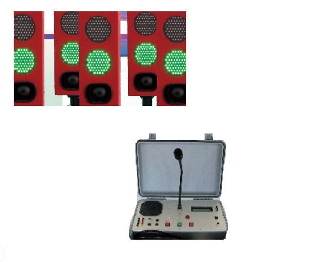


Light System
The light system serves to control the start procedure and to indicate false starts. It consists of 10 start lights (8 lanes, 2 starter/aligner). The light comes with a red and green light as well as an acoustic signal device.Technical Specification
Starter unit
The starter unit is used to control the start light, pre-start and false start signaling.Technical Specification